Overview:
When computers finally carry out the
steps of an algorithm, the algorithm must be reduced (translated) to a
form that can be recognized and executed by an electronic
device. Computers are designed using "logic circuits", which are
configurations of "gates" interconnected to solve specific
problems. This lab allows you to participate in a logic design
experience to get a feel for the organization of components that make
up a modern computer. The readings and problems for this
assignment are in Chapter 4 of your text.
Be sure to justify your answers! You may do this work either by hand or with a word processor (e.g. MS Word). Also, you may choose to do this assignment either by yourself or in a group. However, solutions should be written up individually and handed in on Monday, at the beginning of class.
To submit a file electronically, you should first rename it so that you are identified as the author (e.g., give it a name like lab-x-ltoma). Then drag the file to the csci107 -> Drop Box folder. Be careful not to drag an entire folder into the Drop Box; only a single file at a time can be submitted.
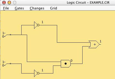
This circuit has two NOT gates, an AND gate and an OR gate.
The output value of each gate is displayed on the wire on its
right. The inputs to the entire circuit are set by toggle
switches on the left - each of these can be 0 or 1. The output
of the entire circuit is shown on the rightmost gate (in this example,
the OR gate).
To change the values of the input switches, select the Changes
-> Set Switches menu item and then click on the switch to be
changed. Note how the outputs of the different gates change in
response.
1. Write down a truth table for this circuit, using A and B
as labels for the two input switches and C for the output value on the
right.
To add a new gate to a circuit, select the Gates -> And
gate,
Gates -> Or gate, or Gates -> Not gate menu item.
Now click on the yellow area to place the gate. To add a
wire that connects the output post of a gate to an input post of
another gate, select Changes -> Connect gates and then click
on the two posts to be connected. To remove a gate from the
circuit, select Changes -> Delete and then click on the gate
to be removed.
Now use these tools to create a circuit that looks like this:
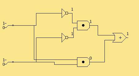
2. Save this circuit as the file <yourlogin>.cir
on the desktop by selecting the File -> Save as menu item.
Drag this file to the csci107 -> Drop Box.
3. Explain briefly in English what this new circuit
accomplishes.